
GoodWe Craftsman edition Installation Guide
Installers note: When the label plaque is installed outdoors, you must attach the provided engraved shutdown procedure, and yellow warning labels directly on top of the aluminium plaque to ensure compliance with AS/NZS 4777.1:2024 clause 6.1(c).
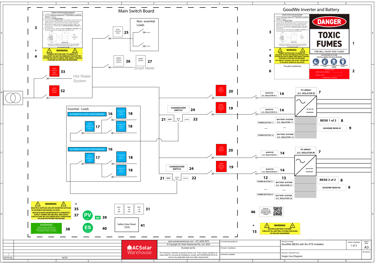
Installation SLD (No GoodWe STS)
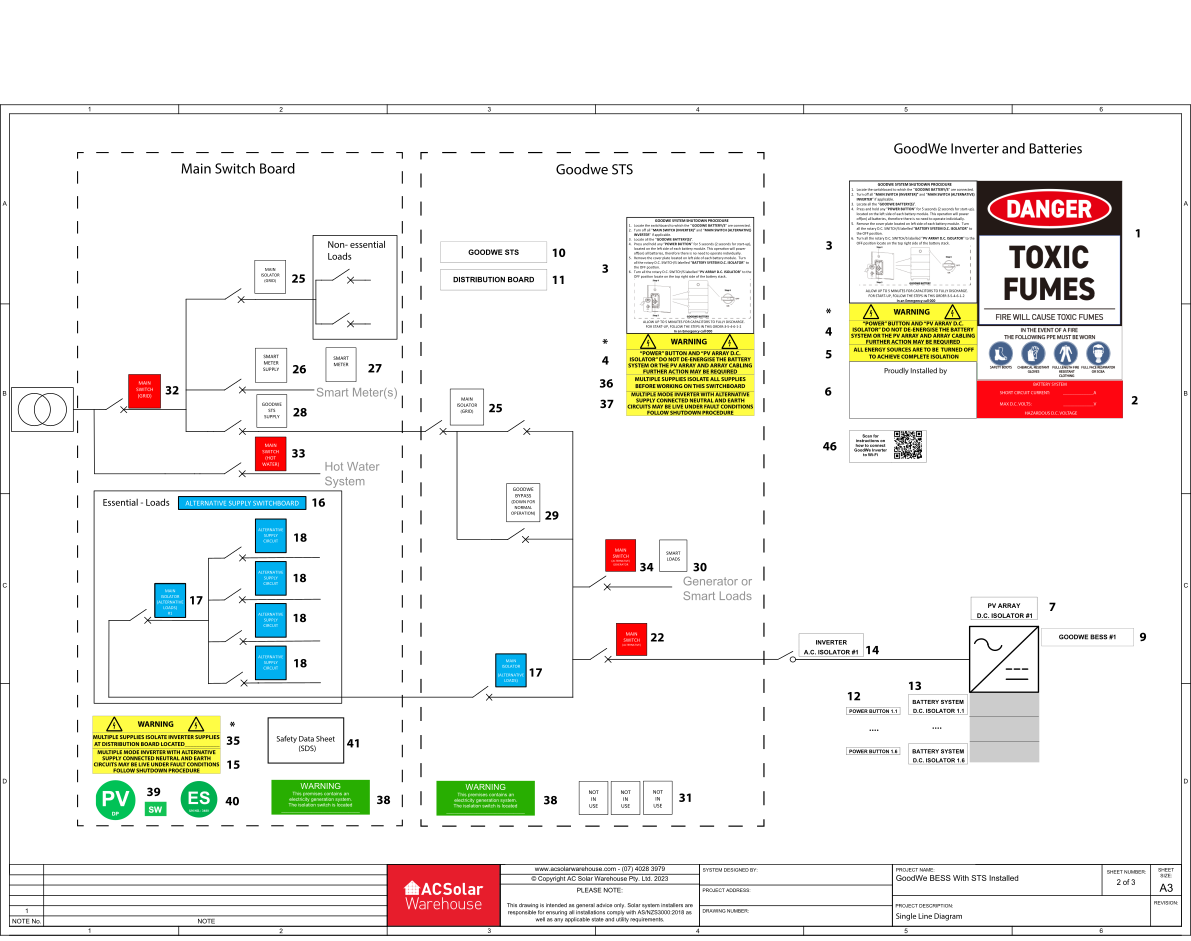
Installation SLD (With GoodWe STS)
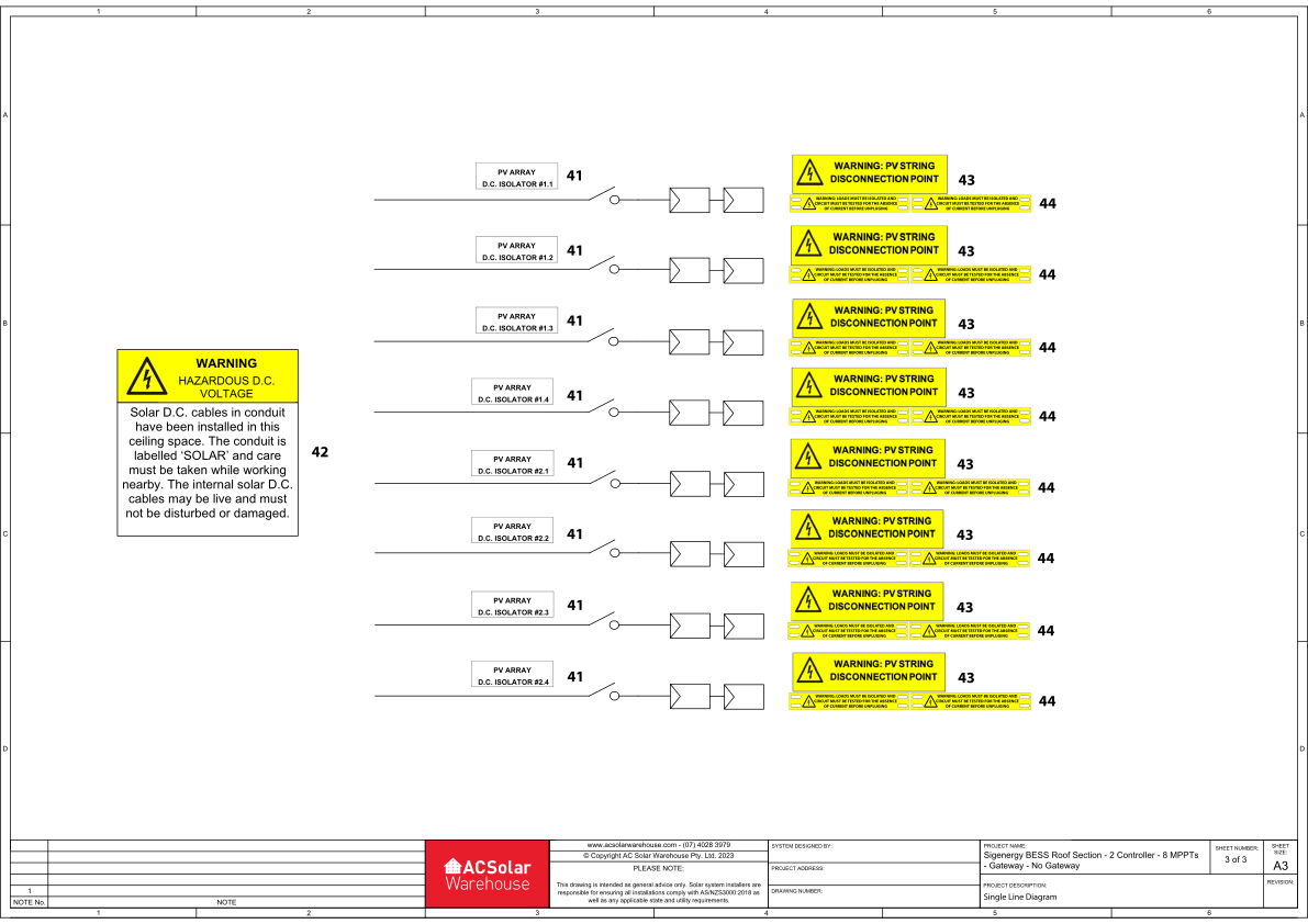
Installation SLD (ROOF SECTION, for the DC Coupled Kit)
GoodWe BESS with Gateway Installed
|
1 |
|
Included in the plaque. To be installed adjacent to battery enclosure or on all doors to the room where the battery is located.
|
|
2 |
|
To be installed adjacent to battery enclosure or on all doors to the room where the battery is located. Current and Voltage values to be filled out according to site specifics.
|
|
3 |
|
To be installed adjacent to the GoodWe battery on top of the plaque and adjacent to the equipment to be operated in event of a shutdown (usually the switchboard the inverter is connected to).
|
|
* |
* Shall be installed above the text |
The warning sign must remain together with the associated warning text. Do not attach individually. Please follow the installation diagram for the correct placement. |
|
4 |
|
To be installed below each shutdown procedure label. |
|
5 |
|
Where both solar and a battery is installed, this label is to be installed adjacent to the inverters. |
|
6 |
|
To be installed on the white space on the bottom left hand side of the plaque (if you wish), or any other location you prefer. Not a required label so can be omitted. Engrave details as you wish or stick your own logo/sticker on top. |
|
7 |
|
To be installed adjacent to each DC Switch (top right side as per shutdown procedure) on the GoodWe batteries. Label kit includes suitable labels if 2 battery systems are installed, if there are more, additional labels need to be sourced. |
|
8 |
|
When more than 1 battery system (stacks of batteries) is installed, these labels shall be installed adjacent to each GoodWe battery. Label kit includes suitable labels if 2 battery systems are installed, if there are more, additional labels need to be sourced. When only 1 battery system is installed, neither of these labels is required. |
|
9 |
|
These labels shall be installed adjacent to each GoodWe inverter. Label kit includes suitable labels if 2 battery systems are installed, if there are more, additional labels need to be sourced. |
|
10 |
|
To be installed on the GoodWe STS for easy identification in the shutdown procedure |
|
11 |
|
To be installed on GoodWe STS or other solar distribution board (when installed) between inverter and MSB. |
|
12 |
|
To be installed adjacent to the power button (left side of each battery module as per shutdown procedure). * Each battery module has a power button on the side. Assumes a maximum of 2 inverters. |
|
13 |
|
To be installed adjacent to each DC Switch (at left side panel as per shutdown procedure) on each GoodWe battery module. Label kit includes suitable labels if 2 battery systems are installed, if there are more, additional labels need to be sourced |
|
14 |
|
If enclosed A.C. isolators are installed between the switchboard and the GoodWe batteries, install these labels adjacent to the relevant isolator/s. |
|
15 |
|
When more than 1 battery system (stacks of batteries) is installed, this label is required to be installed adjacent to 1 of the inverters. Not required when only one battery system is installed. |
|
16 |
|
To be installed to the switchboard where the system is configured for whole home backup, or where all load circuits within the distribution board or switchboard are backed up. |
|
17 |
|
Non numbered, and #1/#2 included. To be installed - #1/#2 adjacent to the main isolator for the essential loads . If there is no main isolator for these loads then #1 and #2 are not required - Non numbered is to be installed adjacent to the main isolator on the GoodWe STS if installed |
|
18 |
|
To be installed adjacent to each backed-up circuit. Label kit includes suitable labels for 4 backed-up circuits, if there are more, additional labels need to be sourced. |
|
19 |
|
Labels to be installed adjacent to each switch that the GoodWe inverter backup port are connected to. |
|
20 |
|
Labels to be installed adjacent to each switch that the GoodWe inverter grid port are connected to. |
|
21 |
|
To be installed adjacent to the changeover switch to match the corresponding position |
|
22 |
|
To be installed adjacent to the changeover switch to match the corresponding position |
|
23 |
|
To be installed adjacent to the changeover switch to match the corresponding position |
|
24 |
|
3 included. To be installed adjacent to the changeover switch. |
|
25 |
|
2 included. To be installed: - adjacent to the main isolator for the non-backup loads. If there is no main isolator for these loads (or there is no non-backup loads), this label is not required. - Where the GoodWe inverter is not connected directly to the MSB, this label is to be installed adjacent to the main switch of the switchboard it is connected to. |
|
26 |
|
To be installed adjacent to the switch the GoodWe smart meter is connected to. If GoodWe smart energy meter has not installed, this label is not required. |
|
27 |
|
To be installed adjacent to the GoodWe smart meter. If GoodWe smart meter has not installed, this label is not required. |
|
28 |
|
To be installed adjacent to the switch the GoodWe STS is connected to. If the STS is not installed, this label is not required |
|
29 |
|
To be installed on the bypass breaker located in the GoodWe STS |
|
30 |
|
To be installed adjacent to the smart port breaker located in the GoodWe STS |
|
31 |
|
To be installed adjacent to breakers with unconnected loads |
|
32 |
|
To be installed adjacent to the main switch on the MSB. |
|
33 |
|
To be installed adjacent to the hot water main switch on the MSB. |
|
** |
|
Included to accommodate for installer preferences as an alternative to (alternative) inverter #1 #2 switches. |
|
34 |
|
To be installed to the switch to which the generator is connected to located in the main switchboard or GoodWe STS |
|
35 |
|
To be installed on MSB. 1 label is provided. To be filled out. |
|
36 |
|
To be installed on the switchboard which the GoodWe inverter is directly connected to. |
|
37 |
|
2 included. To be installed on MSB and all distribution switchboards electrically connected between the MSB and the switchboards to which the GoodWe inverter is directly connected (included STS). If both a MSB, a distribution board and an STS are in the same installation, additional labels need to be sourced. |
|
38 |
|
2 included. To be installed on MSB and all distribution switchboards electrically connected between the MSB and the switchboards to which the GoodWe inverter is directly connected. Only required in Victoria. |
|
39 |
|
To be installed on MSB and main metering panel. Label kit includes 1 label assuming the meter panel is the same location as the MSB, if this is not the case an additional label is required. Install the “SW” label on top of the “DP” where rooftop DC isolators are used instead of disconnection points. |
|
40 |
|
To be installed on MSB and main metering panel. Label kit includes 1 label assuming the meter panel is the same location as the MSB, if this is not the case an additional label is required. |
|
41 |
|
To be installed on MSB or meter box and Fire panel. |
|
46 |
|
To be installed in a location of preference near GoodWe BESS |


Roof Section
|
42 |
|
Where DC cabling is installed within a ceiling space, this label is to be installed adjacent to the access point into the ceiling. |
|
43 |
|
To be attached to the PV module or structure within 300mm of all disconnection points (not required if rooftop isolators are used instead of disconnection points). |
|
44 |
|
To be attached (typically zip tied) to positive and negative cables of all disconnection points (not required if rooftop isolators are used instead of disconnection points). |
|
41 |
|
To be installed adjacent on each DC isolator (not required if disconnection points are used instead of rooftop isolators). |


Labels required for all installations, which are not included in our kit.
|
|
To be attached on DC cabling from the array to the inverter at intervals not less than 2m and at every change of direction. These labels are not included in the label kit and must be sourced separately. |
|
|
To be installed on MSB and fire panel shown on a plan (Map or drawing) when the battery system locations that are difficult to find or where the inverter (IES) is not within 3 meters and fully visible from the switchboard. This sign must indicate location of shutdown procedure and inverter. This label is not included in the label kit and must be sourced separately. |
|
|
To be installed on MSB and fire panel shown on a plan (Map or drawing). This label is not included in the label kit and must be sourced separately. |


